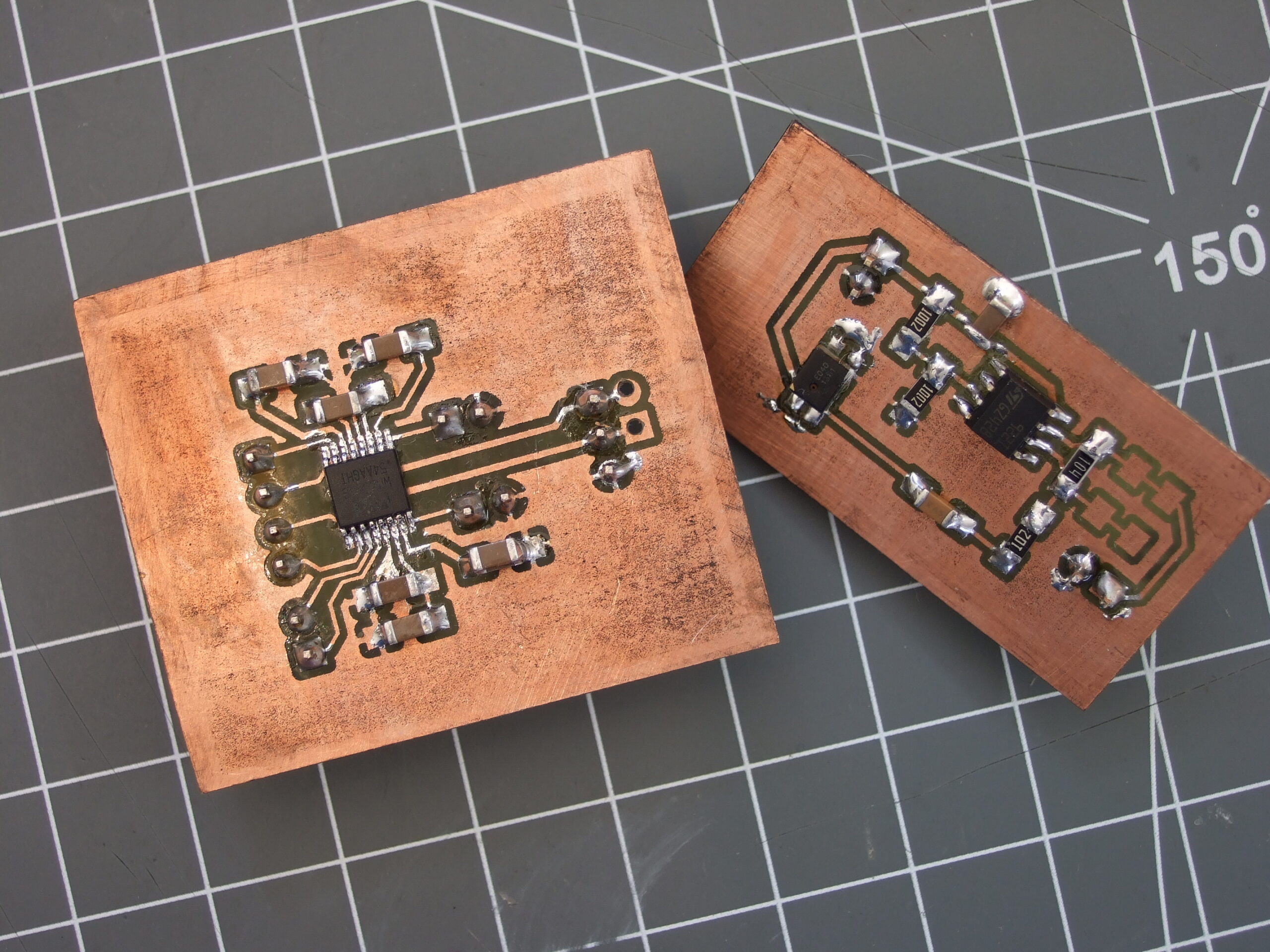
Before I start to discuss the role of PCBs in smart thermometers, you need to understand what is a smart thermometer itself is.
Smart thermometer
A smart thermometer measures the temperature. A smart thermometer has been specifically designed to measure the body temperature and send the data to the user’s phone. Thus, when you use a smart thermometer to record your temperature, the temperature recording is sent to your phone. Your current temperature as well all your previously recorded temperatures, are stored in the app on your phone. If you wish to see a consolidated chart of your data from a few months, you can give the command in the app, and you will receive consolidated data of your temperature range over the last few months.
Role of PCBs in smart thermometers
Consider PCB to be the brain of the thermometer. The thermometer is responsible for measuring the temperature. But who is giving the command to the thermometer to measure the temperature? That is PCB. These printed circuit boards act as the motherboard of the thermometer giving them the commands that need to be carried out. If you wish to see a consolidated debt of your temperature, this action will also be performed by a PCB. Without PCB, a smart thermometer cannot function.
With the requirement of smaller and more powerful devices, the manufacture of flawless PCBs has become difficult. If there is any issue with the PCB, the defect can cause the thermometer to either malfunction or not measure accurate temperatures. If you are looking for defects component inspection, check out defect component inspection Malaysia. This is done by MTSC solution company. They are experts in manufacturing test equipment for the testing of PCBs.
You must make sure that the manufacturing process of the PCB is flawless so that the equipment which is manufactured down the line with those PCB circuits is perfect.
The common defects inspected by these equipment are
- Wrong orientation
- Misalignment of the components
- Defective non-electrical and electrical equipment
- Opens and shorts
- Inconsistent soldering
- Wrong components placement
- Missing electrical components et cetera
There are many ways to check for the correct PCB assembly and inspection.
Visual inspection.
As the name suggests, visual inspection is conducted by checking the PCB manually. This is the most commonly known inspection.
X-ray inspection
X-ray inspection allows the BBC to be inspected for misalignment, salary, and components. The x-rays are focused on the components. The PCB components absorb the x-rays and produce an image which is then used by the manufacturer to identify any wiring issues et cetera
Automated optical inspection (AOI)
This method uses a video camera to scan the circuit and take images. The images are then compiled to generate a report which indicates if any of the defects are present.
Suppose you’re planning to buy a smart thermometer, checkout smart thermometer Malaysia. As mentioned before, MTSE solutions produce PCB circuit testers as well as smart thermometers. You cannot go wrong with MTSC solution


